LCD based digital alarm clock using 89S51 microcontroller | Arrogance Gizmo

LCD based digital alarm clock using 89S51 microcontroller

Thursday 1 March 2012


 Circuit Diagram
An alarm clock is a clock that indicates a pre-set time by producing sound at that time. This functionality of digital clock is used to awaken people or remind them of something. A digital clock is one that displays time digitally. The project explained here, displays time on a 16x2 LCD module. The LCD is interfaced with 8051 microcontroller (AT89S51). This circuit can be used in cars, houses, offices etc.

This clock works in 12 hour mode and is configured by programming the microcontroller AT89S51. The program uses a delay function for producing a delay of 1 second.
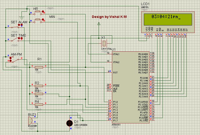
The connections in the circuit are as following: port P2 of microcontroller is used as data input port which is connected to data pins (7-14) of LCD. P3^0, P3^1 and P3^6 pins of microcontroller are connected to control pins RS, RW and EN of LCD. P1^0, P1^1, P1^2 and P1^3 pins of microcontroller are connected to tactile switches to take manual inputs.

On reset, the LCD prompts the user to set alarm. Only the hour and minute components can be set by pressing the corresponding switches, repeatedly. These switches are made active low and so they provide ground to the corresponding input pins of the microcontroller AT89S51. The AM/PM mode is set by toggling the switch between ground and Vcc. Ground would set the clock in AM mode while Vcc would set it in PM mode.


After that the LCD prompts the user to set time. Only the hour and minute components can be set by pressing the corresponding switches, repeatedly. These switches are made active low and so they provide ground to the corresponding input pins of the controller. The AM/PM mode is set by toggling the switch between ground and Vcc. Ground would set the clock in AM mode while Vcc would set it in PM mode. The clock starts when start pin is connected to Vcc by pressing the switch.

The set time is displayed on LCD screen and changes as the time passes on. Seconds are increased after every one second by making use of delay function. As second reaches 59, minute is incremented by one and second is reset to 0. Similarly, as minute reaches 59, hour is increased by one and minute is set to 0. After hour reaches 11, minute reaches 59 and second reaches 59, all of them are set to 0 and the AM/PM mode is changed accordingly.


CODE


When the clock time becomes equal to the alarm time, a message ‘Alarm’ is displayed on LCD and alarm pin of microcontroller goes high for some duration. This pin can be connected to a speaker or buzzer to sound the alarm at the pre-set time.

Comments

4 Comments

RSS
  1. Hello vishal, i really liked your post and your hard work after this post so i am publishing your project at Genius Devils as featured post hope you don't mind.

    ReplyDelete
  2. Its OK, but don't forget a link back to my blog.

    ReplyDelete
  3. thank you for sharing the circuit diagram.....

    arduino kits australia

    ReplyDelete

Copyright @ 2013 Arrogance Gizmo |

Follow Us On Facebook

Labels

.Net (2) 1 KM Range Wireless (1) 16x2 Character LCD (9) 2 UART (1) 4x3 Keypad (1) 4x4 keypad (1) 8051 (5) 8051 Project (2) 8051 Projects (1) 8051 Tutorial (3) 89C51 (4) 89C51 Project (2) 89S51 (1) 89S52 (1) Additional UART (1) Android (3) Android AVD (1) Android Programming Tutorial (1) Android Tutorial (2) Arduino Board (1) ARM Projects (1) Atiny (1) Atmega8 (1) AVR (5) AVR Projects (1) Build From Scratch (1) C# (1) C# Serial Port (2) C# serial Terminal (1) C# Voltmeter (1) Camera (1) Clock (1) Digital Voltmeter (2) Digital watch (1) DIY (2) EEPROM (2) Electronic code lock (1) Embedded (16) Embedded Project (9) Embedded Projects (2) Embedded Tutorial (12) Embeded (4) Extra UART (1) Flutter (1) Getting Started With Android (2) Home Security (1) Internet Based Device Control (1) Java of Things (1) Keypad (1) Keypad Tutorial (1) LCD (6) LCD Tutorial (4) Linux (1) Lock (1) LPG Sensor (1) MAX232 (3) Microcontroller (14) Microcontroller generates sound (1) Microcontroller Interrupt (1) Microcontroller Project (5) Microcontroller Tutorial (11) Microcontroller Tutorial. 8051 Tutorial (1) Mikoc 4 Bit LCD (3) MikroC (14) MikroC AVR (3) MikroC AVR Tutorial (3) MikroC EEPROM (2) MikroC for 8051 (4) MikroC Getting Started (1) MikroC PIC Tutorial (6) MikroC Tutorial (3) Motor Control (1) NETMF (1) New Embedded Boards (2) Optical Mouse (1) Optical Mouse To Camera (1) Password Lock (1) PC Based Voltmeter (1) PIC (7) PIC Based Electronic Lock (1) PIC 12F629 (1) PIC ADC (2) pic interrupt (1) PIC Music (1) pic project (1) PIC Projects (1) PIC sound melody (1) PIC Tutorial (3) PIC UART (1) PIC Voltmeter (2) Project (8) Quadcopter (1) Real Time Monitoring (1) RF (1) Robotic Projects (1) RS 232 (1) Run Android On PC (1) Security System (1) Serial Communication (3) Single Bord Computer (1) Smart home (1) Smart Home Project (1) STM32 (4) STM32F4 (3) STM32F4 Discovery (3) STM32F4 Project (1) STM32F4 Tutorials (3) STMicroelectronics (1) Temperature Sensor (2) Timer (1) Tutorial (8) UART (6) Udoo (1) USB (1) USB to RS 232 (1) USB to UART (1) VISUAL STUDIO (1) Water Level Control (1) WiFi (1)

Search This Blog

Popular Posts