Microcontroller Project | Arrogance Gizmo

Automatic Water Level Control And Real Time Monitoring

Friday, 9 November 2012


Automatic Water Level Control And Real Time Monitoring


Description

This project will control the water level and keep the level between two predefined upper and lower positions. Any sensors can be used for this project, condition is only that it should give an active low output when activated by water. Sensors are simply water activated switches which is connected to ground.

I personally prefer read switch-magnet arrangement. Read switches are fixed on water tank wall at desired positions, and magnet is fixed on a thermocol sheet which floats in water. Modify this idea by experimenting, for an accurate result.

The designing of sensor arrangement is shown above. Sensors are read switches connected between PORT pins and ground. There is a magnet fixed on a thermocol which floats on water. Thermocol is free to move up and down through the string with the water level. When the thermocol reaches predefined water-levels the magnet and read switch come in contact and the read switch is activated and water level is detected. This is not an ultimate design, but just a design idea.


Code

/**********************************************/
/*

 http://www.facebook.com/EmbeddedProjects

 http://microcontrollerprojects00.blogspot.in/

 Author: Vishal K M

 uC:AT89S52
 Compiler: mikroC
 Crystal freq: 12MHz


                                                                                            */
/**********************************************/

extern sfr sbit motor;
sbit LCD_RS at P1_0_bit;
sbit LCD_EN at P1_1_bit;

sbit LCD_D4 at P1_2_bit;
sbit LCD_D5 at P1_3_bit;
sbit LCD_D6 at P1_4_bit;
sbit LCD_D7 at P1_5_bit;
sbit motor at P0_0_bit;

char txt1[] = "Water Level";
char txt2[] = "FULL";
char txt3[] = "MEDIUM";
char txt4[] = "LOW";
char txt5[] = "EMPTY";
 //unsigned int data;


void main() {

P2=0XFF;
P1=0x00;
//P0=0x00;
  Lcd_Init();


while(1)
{
while(P2.F2==1)
{
Lcd_Cmd(_LCD_CLEAR);
Lcd_Out(1,1,txt1);

motor=1;                             //motor off
switch(~P2)
{
case 0: Lcd_Out(2,6,txt5); break;
case 1:Lcd_Out(2,6,txt4); break;
case 3: Lcd_Out(2,6,txt3); break ;

default: ;

}
Delay_ms(500);
                           //motor on

}   motor=0;

 }

}

Electronic Voting Machine Using 8051 Microcontroller (AT89C51)

Friday, 16 March 2012


Circuit

Electronic voting machine has now replaced the traditional mechanism of voting due to several advantages like security, automatic counting etc. This project presents a way to develop an electronic voting machine which displays the count of votes on a 16x2 LCD interface. A user can get his/her vote register through a set of switches (one for each candidate). After every cast of vote, the subsequent count can be seen on LCD. The circuit uses AT89C51 microcontroller and the code for the project has been written in C.

This LCD based electronic voting machine is designed for four candidates. The input part consists of a set of six tactile switches. The switches and 16x2 LCD are interfaced to microcontroller AT89C51 for various operations and displays.

The provision of casting votes for the candidates has been provided through four of these switches. These switches are made active high and connected to pins 2-5 (P1^1 – P1^4) of the controller. The remaining two switches (both active low) are to start and stop the voting procedure. They are connected to pins 1 and 6 (P1^0 and P1^5) respectively. The Init (start) switch initializes the voting system when pressed, while the Stop switch ends the voting and displays the poll results on LCD screen.

For more details on working with LCD, refer LCD interfacing with 8051. The data pins of the LCD (pins 7-14) are connected to the output port P2 of the microcontroller. The control pins (RS, R/W and EN) are connected to port P3 pins P3^0, P3^1 & P3^6 respectively.

Working:
The voting is started by pressing the Init switch after which the user is prompted to vote. The count of votes is stored in four different variables. As soon as the user votes for a candidate by pressing one of the switches, the value of the corresponding variable is increased by one. After this a Thank you message is displayed on LCD to acknowledge the registration of user’s vote.

The message stays on the screen until the next user either presses the Init button to cast another vote or Stop switch is pressed get the poll results. When the stop button is pressed, the names of the candidates are displayed along with their vote counts. After some delay, the result is displayed which could be either declaration of the winner candidate or the candidates with a clash of their number of votes. 

PIC Countdown Timer (0-99) (PIC 16F628A)

Sunday, 4 March 2012


This project describes how to program PIC16F628A to function as a 00-99 min programmable timer. User can set any time between 00-99 minutes and can turn ON a device for that period. The device will be automatically turned OFF after the time expires. For demonstration, the ON/OFF condition of device is simulated by switching LED ON and OFF. With the use of three input switches (unit, ten, start/stop) the user can set ON time of the timer and can also control Start/Stop operation. The two time set switches are for selecting unit and tens digit of minute time interval (00-99). Once you set the value of minute interval, pressing the Start/Stop will turn the timer ON (LED will glow), and pressing the same button again at any point of time during timer operation will interrupt the process (LED will turn OFF) and the timer will be reset. LCD display will provide timer status and user interface for setting time.


Circuit


Code
Compiled using MikroC for PIC


/*
  ############################################


  MCU:16F628A
  Project: PIC Countdown Timer (0-99)
  Vishal K M
  Jan 10, 2012
  ############################################

 
*/

// LCD module connections
sbit LCD_RS at RA0_bit;
sbit LCD_EN at RA1_bit;
sbit LCD_D4 at RB4_bit;
sbit LCD_D5 at RB5_bit;
sbit LCD_D6 at RB6_bit;
sbit LCD_D7 at RB7_bit;
sbit LCD_RS_Direction at TRISA0_bit;
sbit LCD_EN_Direction at TRISA1_bit;
sbit LCD_D4_Direction at TRISB4_bit;
sbit LCD_D5_Direction at TRISB5_bit;
sbit LCD_D6_Direction at TRISB6_bit;
sbit LCD_D7_Direction at TRISB7_bit;
// End LCD module connections

// Tact switches and Relay ports
sbit Relay at RA3_bit;
sbit SS_Select at RB0_bit;    // Start Stop Timer Select
sbit Unit_Button at RB1_bit;  // Set unit min
sbit Ten_Button at RB2_bit;   // Set ten min


// Messages
char Message1[]="Timer by VISHAL";
char Message2[]="Device ON";
char Message3[]="Device OFF";
char Message4[]="Set Time:    min";
char Message5[]="Time Left:   min";
unsigned short i, j, unit=0, ten=0, ON_OFF=0, index=0, clear, time;
char *digit = "00";
// 300ms Delay
void Delay_300(){
 Delay_ms(300);
}

void Display_Digits(){
 digit[1]=unit+48;
 digit[0]=ten+48;
 Lcd_Out(2,11,digit);
}

void start_timer(unsigned short MinVal){
 unsigned short temp1, temp2;
 Relay = 1;
 ON_OFF = 1;
 Lcd_Cmd(_LCD_CLEAR);
 Lcd_Out(1,1,Message2);
 Lcd_Out(2,1,Message5);
 OPTION_REG = 0x80 ;
 INTCON = 0x90;
 for (i=0; i<MinVal; i++){
  temp1 = (MinVal-i)%10 ;
  temp2 = (MinVal-i)/10 ;
  Lcd_Chr(2, 12, temp2+48);
  Lcd_Chr(2, 13, temp1+48);
  j=1;
  do {
  Delay_ms(1000);
  j++;
  } while(((j<=60) && (Clear ==0)));
  if (Clear) {
   Relay = 0;
   Delay_ms(500);
   Lcd_Out(1,1,Message3);
   INTCON = 0x00;
   goto stop;
   }
 }
 stop:
 Relay = 0;
 ON_OFF = 0;
 unit = 0;
 ten = 0;
 clear = 1;
}

void interrupt(void){
  if (INTCON.INTF == 1)   // Check if INTF flag is set
   {
    Clear = 1;
    INTCON.INTF = 0;       // Clear interrupt flag before exiting ISR
   }
  }

void main() {
  CMCON  |= 7;                       // Disable Comparators
  TRISB = 0b00001111;
  TRISA = 0b11110000;
  Relay = 0;

  Lcd_Init();                        // Initialize LCD
 start:
  clear = 0;
  Lcd_Cmd(_LCD_CLEAR);               // Clear display
  Lcd_Cmd(_LCD_CURSOR_OFF);          // Cursor off
  Lcd_Out(1,1,Message1);
  Lcd_Out(2,1,Message4);
  Display_Digits()  ;
 do {

     if(!Unit_Button){
     Delay_300();
     unit ++;
     if(unit==10) unit=0;
     Display_Digits();
    } // If !Unit_Button

    if(!Ten_Button){
     Delay_300();
     ten ++;
     if(ten==10) ten=0;
     Display_Digits();
    } // If !Ten_Button

    if(!SS_Select){
     Delay_300();
     time = ten*10+unit ;
     if(time > 0) start_timer(time);
    } // If !SS_Select

    if(clear){
     goto start;
    }
   } while(1);
}


Facebook page 

PIC Microcontroller Based Electronic Lock (PIC16F877A)

Friday, 2 March 2012
 Circuit Diagram

Security is a prime concern in our day-today life. Everyone wants to be as much secure as possible. An access control for doors forms a vital link in a security chain. The microcontroller based digital lock for Doors is an access control system that allows only authorized persons to access a restricted area.
An electronic lock or digital lock is a device which has an electronic control assembly attached to it. They are provided with an access control system. This system allows the user to unlock the device with a password. The password is entered by making use of a keypad. The user can also set his password to ensure better protection. The major components include a Keypad, LCD and the controller PIC16F877A. This article describes the making of an electronic code lock using the 16F877A microcontroller.

The system is fully controlled by the 8 bit microcontroller 16F877A which has a 8Kbytes of ROM for the program memory. The password is stored in the EPROM so that we can change it at any time. The system has a Keypad by which the password can be entered through it. When the entered password equals with the password stored in the memory then the relay gets on and so that the door is opened.

The code is built in a modular style to allow a user to find ways to modify  project. In start the D Lock programs loads with a default code of "2345" format is *2345# which can be enter to unlock the door, the code cam be change by entering the master code in the format *23455#new 4 digit code.  In this program i only display the result on LCD and lock will be  placed at   PORTA bit 0 where i put led for simulation. 


A 4x3 matrix keypad and a 16x2 LCD have been used here. Keypad and LCD are very commonly used input & output devices, respectively. The password is stored in the system EEPROM.
While unlocking, if the entered password from keypad matches with the stored password, then the lock opens and a message is displayed on LCD. Also an output pin is made high to be used for further purpose..

As the program starts, wait for 5sec and press * string ‘Enter Password’ is displayed on LCD. The keypad is scanned for pressed digits one by one. Every time, row and column of the key pressed is detected and is displayed on LCD. After the four digits are entered, the user should press # to Confirm Password and again the input is taken through LCD. If the passwords do not match, a message is displayed to indicate ‘Access Denied’ otherwise the ‘Access Granted’ message.

The default password is 2345 and master key to change password is 23455., entry begins with * and stops with #.

Update 28-8-2013

 1. Here two circuit are provided, the smaller one works only for 

simulation and the larger one works only    in real world( Problem

with Pull Down resistors)

2. Due to frequent Requests I have Uploaded the HEX(8Mhz Crystal) file of these project in Our Facebook Group-Click Here

Code 


  Discussion Group


Facebook Page                                                                                                                  Contents Page


Check Our New Blog: Embedded Projects-Tutorials-Arduino-Android-Raspberry PI- Gadgets News - Embedded Hackes - New Embedded Products Intro etc 

 (click the Image Below to Visit the Blog)

www.google.co.in/url?sa=t&rct=j&q=&esrc=s&source=web&cd=1&cad=rja&ved=0CCoQFjAA&url=http%3A%2F%2Farrogancegizmo.blogspot.com%2F&ei=SMaRUsGzCYj_rAfA-4GoDw&usg=AFQjCNEw6Pm6VepdEnZlm1evPy5f0N2NdA&sig2=sG5PkXDQilaUfIan6u2Wzw&bvm=bv.56988011,d.bmk
 

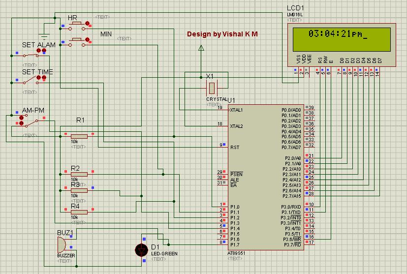
LCD based digital alarm clock using 89S51 microcontroller

Thursday, 1 March 2012


 Circuit Diagram
An alarm clock is a clock that indicates a pre-set time by producing sound at that time. This functionality of digital clock is used to awaken people or remind them of something. A digital clock is one that displays time digitally. The project explained here, displays time on a 16x2 LCD module. The LCD is interfaced with 8051 microcontroller (AT89S51). This circuit can be used in cars, houses, offices etc.

This clock works in 12 hour mode and is configured by programming the microcontroller AT89S51. The program uses a delay function for producing a delay of 1 second.
The connections in the circuit are as following: port P2 of microcontroller is used as data input port which is connected to data pins (7-14) of LCD. P3^0, P3^1 and P3^6 pins of microcontroller are connected to control pins RS, RW and EN of LCD. P1^0, P1^1, P1^2 and P1^3 pins of microcontroller are connected to tactile switches to take manual inputs.

On reset, the LCD prompts the user to set alarm. Only the hour and minute components can be set by pressing the corresponding switches, repeatedly. These switches are made active low and so they provide ground to the corresponding input pins of the microcontroller AT89S51. The AM/PM mode is set by toggling the switch between ground and Vcc. Ground would set the clock in AM mode while Vcc would set it in PM mode.


After that the LCD prompts the user to set time. Only the hour and minute components can be set by pressing the corresponding switches, repeatedly. These switches are made active low and so they provide ground to the corresponding input pins of the controller. The AM/PM mode is set by toggling the switch between ground and Vcc. Ground would set the clock in AM mode while Vcc would set it in PM mode. The clock starts when start pin is connected to Vcc by pressing the switch.

The set time is displayed on LCD screen and changes as the time passes on. Seconds are increased after every one second by making use of delay function. As second reaches 59, minute is incremented by one and second is reset to 0. Similarly, as minute reaches 59, hour is increased by one and minute is set to 0. After hour reaches 11, minute reaches 59 and second reaches 59, all of them are set to 0 and the AM/PM mode is changed accordingly.


CODE


When the clock time becomes equal to the alarm time, a message ‘Alarm’ is displayed on LCD and alarm pin of microcontroller goes high for some duration. This pin can be connected to a speaker or buzzer to sound the alarm at the pre-set time.

Copyright @ 2013 Arrogance Gizmo |

Follow Us On Facebook

Labels

.Net (2) 1 KM Range Wireless (1) 16x2 Character LCD (9) 2 UART (1) 4x3 Keypad (1) 4x4 keypad (1) 8051 (5) 8051 Project (2) 8051 Projects (1) 8051 Tutorial (3) 89C51 (4) 89C51 Project (2) 89S51 (1) 89S52 (1) Additional UART (1) Android (3) Android AVD (1) Android Programming Tutorial (1) Android Tutorial (2) Arduino Board (1) ARM Projects (1) Atiny (1) Atmega8 (1) AVR (5) AVR Projects (1) Build From Scratch (1) C# (1) C# Serial Port (2) C# serial Terminal (1) C# Voltmeter (1) Camera (1) Clock (1) Digital Voltmeter (2) Digital watch (1) DIY (2) EEPROM (2) Electronic code lock (1) Embedded (16) Embedded Project (9) Embedded Projects (2) Embedded Tutorial (12) Embeded (4) Extra UART (1) Flutter (1) Getting Started With Android (2) Home Security (1) Internet Based Device Control (1) Java of Things (1) Keypad (1) Keypad Tutorial (1) LCD (6) LCD Tutorial (4) Linux (1) Lock (1) LPG Sensor (1) MAX232 (3) Microcontroller (14) Microcontroller generates sound (1) Microcontroller Interrupt (1) Microcontroller Project (5) Microcontroller Tutorial (11) Microcontroller Tutorial. 8051 Tutorial (1) Mikoc 4 Bit LCD (3) MikroC (14) MikroC AVR (3) MikroC AVR Tutorial (3) MikroC EEPROM (2) MikroC for 8051 (4) MikroC Getting Started (1) MikroC PIC Tutorial (6) MikroC Tutorial (3) Motor Control (1) NETMF (1) New Embedded Boards (2) Optical Mouse (1) Optical Mouse To Camera (1) Password Lock (1) PC Based Voltmeter (1) PIC (7) PIC Based Electronic Lock (1) PIC 12F629 (1) PIC ADC (2) pic interrupt (1) PIC Music (1) pic project (1) PIC Projects (1) PIC sound melody (1) PIC Tutorial (3) PIC UART (1) PIC Voltmeter (2) Project (8) Quadcopter (1) Real Time Monitoring (1) RF (1) Robotic Projects (1) RS 232 (1) Run Android On PC (1) Security System (1) Serial Communication (3) Single Bord Computer (1) Smart home (1) Smart Home Project (1) STM32 (4) STM32F4 (3) STM32F4 Discovery (3) STM32F4 Project (1) STM32F4 Tutorials (3) STMicroelectronics (1) Temperature Sensor (2) Timer (1) Tutorial (8) UART (6) Udoo (1) USB (1) USB to RS 232 (1) USB to UART (1) VISUAL STUDIO (1) Water Level Control (1) WiFi (1)

Search This Blog

Popular Posts